Programmable Logic Controllers 2025 pdf epub mobi 电子书
简体网页||繁体网页
Programmable Logic Controllers 2025 pdf epub mobi 电子书 著者简介
Dag H. Hanssen is a professor with the University of Tromso.
Programmable Logic Controllers 电子书 图书目录
下载链接在页面底部
下载链接1
下载链接2
下载链接3
发表于2025-03-22
Programmable Logic Controllers 2025 pdf epub mobi 电子书
Programmable Logic Controllers 2025 pdf epub mobi 电子书
Programmable Logic Controllers 2025 pdf epub mobi 电子书
喜欢 Programmable Logic Controllers 电子书 的读者还喜欢
Programmable Logic Controllers 电子书 读后感
评分
评分
评分
评分
评分
类似图书 点击查看全场最低价
出版者:WILEY
作者:Dag Hakon Hanssen
出品人:
页数:564
译者:
出版时间:2015
价格:0
装帧:平装
isbn号码:9781118949245
丛书系列:
图书标签: PLC 2020
Programmable Logic Controllers 2025 pdf epub mobi 电子书 图书描述
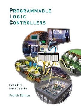
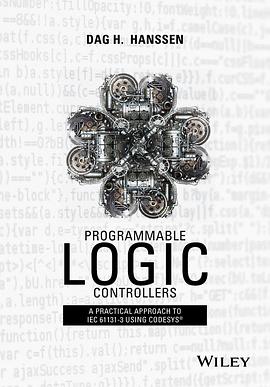
IEC61131-3 is the attempt by the industry automation community to unify the programming language and methodology for PLC. This book offers a through introduction to the PLC itself, the basic idea of programming a PLC for a control process, and the implementation of these general concepts using CODESYS software, which is a widely recognized instance of the IEC61131-3 standard.
Programmable Logic Controllers 2025 pdf epub mobi 电子书
Programmable Logic Controllers 2025 pdf epub mobi 用户评价
评分
评分
评分
评分
评分
Programmable Logic Controllers 2025 pdf epub mobi 电子书
分享链接
Programmable Logic Controllers pdf 下载
Programmable Logic Controllers epub 下载
Programmable Logic Controllers mobi 下载
Programmable Logic Controllers txt 下载


Programmable Logic Controllers 2025 pdf epub mobi 电子书 下载链接


Programmable Logic Controllers 2025 pdf epub mobi 电子书 下载链接
相关图书
-
 西门子S7系列PLC的应用与维护 2025 pdf epub mobi 电子书
 -
 电气控制与PLC控制技术 2025 pdf epub mobi 电子书
 -
 PLC操作实训 2025 pdf epub mobi 电子书
 -
 图解PLC控制系统梯形图和语句表 2025 pdf epub mobi 电子书
 -
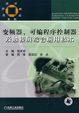
 变频器、可编程序控制器及触摸屏综合应用技术 2025 pdf epub mobi 电子书
 -
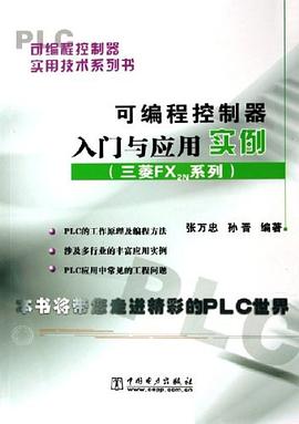
 可编程控制器入门与应用实例 2025 pdf epub mobi 电子书
 -
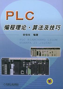
 PLC编程理论·算法及技巧 2025 pdf epub mobi 电子书
 -
 PLC分析与设计应用 2025 pdf epub mobi 电子书
 -
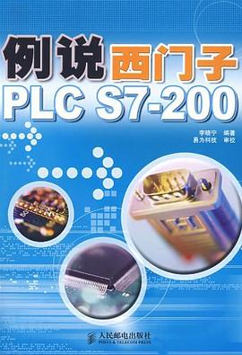
 例说西门子PLC S7-200 2025 pdf epub mobi 电子书
 -
 三菱FX系列PLC应用系统设计指南 2025 pdf epub mobi 电子书
 -
 欧姆龙CP1系列PLC原理与应用 2025 pdf epub mobi 电子书
 -
 高速电力线通信系统 2025 pdf epub mobi 电子书
 -
 PLC、现场总线及工业网络实用技术速成 2025 pdf epub mobi 电子书
 -
 Programmable Logic Controllers 2025 pdf epub mobi 电子书
 -
 电力线通信技术 2025 pdf epub mobi 电子书
 -
 西门子S7-200 PLC工程应用技术教程 2025 pdf epub mobi 电子书
 -
 可编程序控制器原理及应用-第二版 2025 pdf epub mobi 电子书
 -
 零起步轻松学PLC技术 2025 pdf epub mobi 电子书
 -
 数控机床PLC控制技术 2025 pdf epub mobi 电子书
 -
 可编程序控制器原理与应用基础 2025 pdf epub mobi 电子书

